Key features:
RM-01
Modbus to wireless mesh network converter
- Direct cable replacement for Modbus RTU installations
- DIN rail mountable
- 12-28 DC voltage power supply
- RS-485 interface with configurable baudrate
- Full functional isolation between all ports
- License free 868MHz radio interface
- Secure radio transmission
- Dual antenna with antenna diversity for improved reliability
- Seamless operation in a wireless mesh network with multiple hops
- Mini-USB configuration interface with a dedicated application
- Quick installation and setup
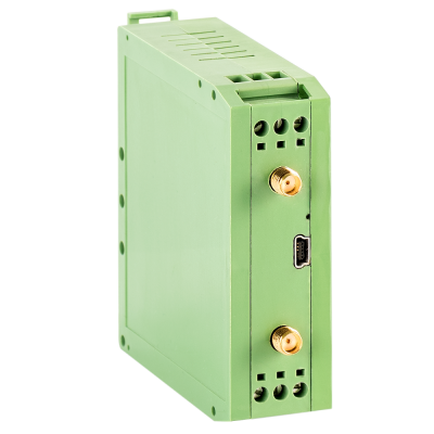
The RM-01 is a Modbus to wireless mesh network converter that can easily replace the cabling in Modbus driven automation installations. The device can be mounted on a standard DIN rail and can be powered from a 12-28V DC source. It features a RS-485/Modbus RTU interface and can act both as a Modbus master or Modbus slave.
The RM-01 devices seamlessly form a wireless mesh network with up to 4 network hops. The network consists of a single RM-01 configured as Modbus master and multiple other RM-01 devices configured as Modbus slaves. The Modbus packet sent via RS-485 interface to the master is forwarded to all the slaves, and the answer from slaves is forwarded to the master, so that the network acts as a directed cable replacement.
The RM-01 devices feature a dual antenna SMA outputs for improved reliability. The integrated, advanced radio frequency front-end allows the devices to operate even in the presence of strong electromagnetic interference, typical for industrial environments.
Overview
The RM-01 devices are designed to automatically form a wireless mesh network upon being powered on. In this radio network one RM-01 device that is connected to a Modbus master (typically SCADA or PLC) is configured to work in master mode, while the other devices, connected to Modbus slaves are configured in slave mode. The job of the RM-01 devices configured in slave mode is to detect (using the Modbus slave detection mechanism described below) the addresses of each and every Modbus device connected to a particular RM-01. This information is sent to the RM-01 master device. In such network, each time the Modbus master sends out a command, the RM-01 that is working in master mode forwards this message to the proper RM-01 working in slave mode, to which the recipient of the Modbus packet is connected. If a Modbus packet is produced in response, the RM-01 slave sends it back to the RM-01 master, which in turn forwards it to the Modbus master device.
Mode of operation
The RM-01 can be configured to work in two modes:
- the master mode, in which it is connected to a single Modbus master device
- the slave mode, in which it is connected to one or more Modbus slave devices
In master mode, the RM-01 accepts Modbus requests from a Modbus master device (typically SCADA or PLC). Each time a valid Modbus packet is received, the RM-01 decodes the request and checks, if the recipient of the packet is known, meaning that the RM-01 master knows to which of the RM-01 slaves this Modbus packet should be forwarded. If the recipient is known, the packed is forwarded to this particular RM-01 slave. In cases when the recipient is not known, the RM-01 master broadcasts the request to all RM-01 slaves, expecting response from one of them. If the response is received, the RM-01 replies to the Modbus master device and saves the information about the origin of the response. This way, next time the request to this Modbus address is issued, the master RM-01 knows to which RM-01 slave it should be forwarded.
In slave mode, after being powered up the RM-01 first tries to detect the Modbus devices, connected to its RS-485 bus using Modbus slave detection algorithm (described below). Once it?s done, the information about the Modbus devices is sent to the master RM-01. If a Modbus packet is sent to the RM-01 slave, it is being transmitted on the RS-485 bus. If a valid response is received it is being forwarded back to the RM-01 master.
Modbus slave detection
When RM-01 is configured to operate in slave mode it automatically detects the Modbus devices connected to its RS-485 bus. It does that by issuing a READ COIL STATUS (FC=01) with coil (data) address = 0 and data count = 1 to each of the potential Modbus addresses. The scanned address range can be limited using the configuration software. The issued command is a valid Modbus command (with a valid CRC). If a Modbus device with a given address exists on the bus, it should respond with either the READ COIL STATUS RESPONSE or the INVALID REQUEST EXCEPTION. Either way, the RM-01 will then know that a Modbus device with particular address is present on its RS-485 bus. This information is stored in the slave RM-01 operating and also sent to the master RM-01.
The Modbus slave detection algorithm is triggered each time the slave RM-01 device is powered on. It is also triggered remotely by the master RM-01 in case, when the master RM-01 is restarted and it needs to update the information from the field. The scanning procedure has always the lowest priority on the RS-485 bus and does not interfere with the actual Modbus requests and responses.
The RM-01 is configured using a dedicated PC application. The connection is established by connecting the device to a PC using a mini-USB to USB-A standard cable. Consult the device datasheet for the detailed explanation of the settings.
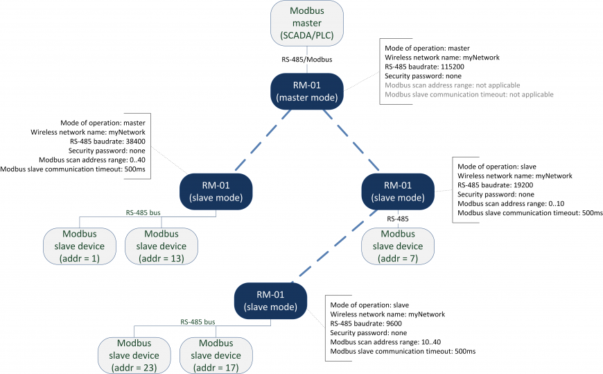
Picture below presents a simple exemplary network consisting of a single Modbus master with an accompanying RM-01 media converter (operating in master mode) and five Modbus slave devices connected through three RM-01 media converters.

The picture also presents an exemplary configuration for each of the RM-01 devices. In order to communicate, each RM-01 must have the same wireless network name (and security password, if set). The RS-485 baud rates can be specified separately for each RM-01 operating in slave mode. Each RM-01 can also scan different range of Modbus addresses with various timeout settings.
Serial interface
|
Protocol: Modbus RTU Master/Slave |
|
|
Number of ports: 1 |
|
|
Serial standard: RS-485 (2wire: Data+, Data-, GND) |
|
|
Isolation: |
functional built-in isolation between RS-485 port and DC power supply antennas |
|
|
functional built-in isolation between RS-485 port and the antennas |
Serial Communication Parameters
|
Data bits: 8 |
|
Stop bits: 1 |
|
Parity: none |
|
Flow control: automatic |
|
Baudrate: 9 600 bps – 115 200 bps (user selectable) |
Modbus
|
Max. no. of devices in the whole network: 255 |
|
Max. no. of devices connected to a single device: 16 |
Radio interface
|
Operating frequency: 868.0 – 868.6MHz |
|
Output power: up to +14dBm (25mW) |
|
Over the air baudrate: 20kbps |
|
Modulation: DSSS-BPSK |
|
Sensitivity: -110dBm |
Antennas
|
No. of antenna connectors: 2 |
|
|
Antenna connector: SMA (female) |
|
|
Antenna impedance: 50Ohm |
|
|
Isolation: |
functional built-in isolation between antennas and RS-485 port |
|
|
functional built-in isolation between antennas and DC power supply |
Configuration interface
|
Configuration connector: mini-USB |
Configuration Software
|
Supported platforms: Windows 7,8,10, Linux |
Power supply
|
Input voltage: 12 to 28 VDC (±15%) |
|
Input current: 300 mA max. |
|
Power connector: Terminal block |
Environmental Limits
|
Operating temperature: -25 to 65°C (-13 to 149°F) |
|
Storage temperature: -40 to 85°C (-40 to 185°F) |
|
Ambient relative humidity: 5 to 95% (non-condensing) |
Certification
|
EMC: |
Device conforms to 2014/30/UE directive |
|
EMI: |
CISPR 22 |
|
EMS: |
IEC 61000-4-2 ESD: Contact: 8 kV; Air: 15 kV |
|
|
IEC 61000-4-3 RS: 80 MHz to 1 GHz: 10 V/m |
|
|
IEC 61000-4-4 EFT: Power: 4 kV; Signal: 2 kV |
|
|
IEC 61000-4-5 Surge: Power: 2 kV; Signal: 2 kV |
Vibration: IEC 60068-2-6, IEC 60068-2-64
Shock: IEC 60068-2-27
Drop: IEC 60068-2-32
Warranty
|
Warranty period: 2 years |
|
Details: see www.embe.tech/warranty |


