Table of Contents
- What you'll need
- Demo architecture
- The embeNET demo package
- Setting up Code Composer Studio IDE
- Programming and debugging the LAUNCHXL-CC1312R1 boards
- Preparing the demo
- Starting the Network
- Virtual network interface
- Visualizing the network
- Network services
- MQTT-SN demo service
- Custom UDP service in the demo application
- Next steps
This document describes how to run the embeNET demo application on the LAUNCHXL-CC1312R1 boards equipped with CC1312R1 chip from Texas Instruments.
What you'll need
- PC with Windows
- One LAUNCHXL-CC1312R1 board connected to the PC (via USB cable) that will act as the root node in the network
- At least one more (up to 10) LAUNCHXL-CC1312R1 boards that will act as the network nodes
- Code Composer Studio, available for download from the official Texas Instrumets site
- embeNET demo package for CC1312
Optionally, to play with the MQTT-SN demo service you'll need:
- MQTT For Small Things (SN) written in Java, available for download from github
- MQTT Client Toolbox, available for download from the official MQTTX page
Optionally, to easily interact with the custom UDP service you'll need
Demo architecture
Picture below presents the architecture of the embeNET network presented in this demo.
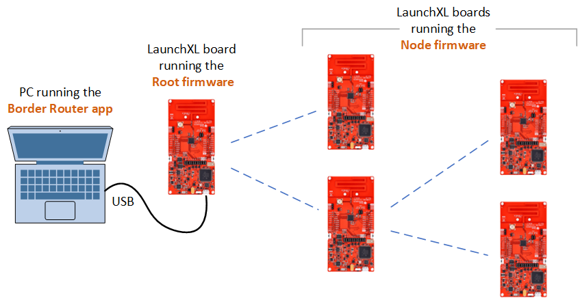
The PC acts as a Border Router and becomes the gateway to the network. One LaunchXL board runnig the Root firmware is connected to the PC via USB cable and acts as a network interface. The other LaunchXL boards are running the Node firmware. When running the Border Router application, it connects to the root using serial connection (COM in Windows) and a new network interface is registered in the system. All other LaunchXL boards then join the network as nodes. Since embeNET is a true mesh network, every node in the network is a router and can extend the network through successive hops.
The embeNET demo package
The embeNET demo package for CC1312 is distributed as a single ZIP file. Unzip it into a convenient location on disk. Inside you'll find a couple of folders:
- doc - contains this documentation
- embenet_br - contains the border router application to run on the PC
- embenet_demo_src - contains the firmware source code for the CC1312 modules
- enms_visualizer - contains a PC demo application that visualizes the network
Setting up Code Composer Studio IDE
In order to build the firmware project you'll need to add two items to the Code Composer Studio IDE:
- SimpleLink CC13xx and CC26xx Wireless MCUs component
- ARM GCC Compiler Tools
We've found that the best method for doing that (at least in CodeComposer 12.5.0) is to go to select "Resource explorer" from the "View" menu.
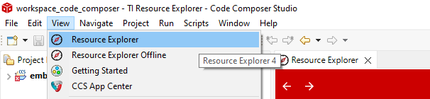
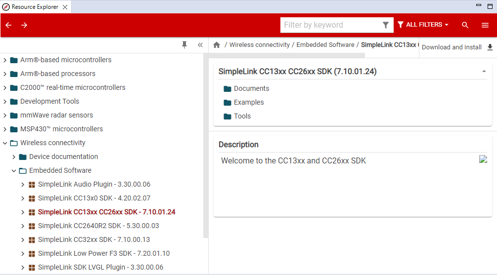
There navigate to "Wireless connectivity" -> "Embedded Software" and select SimpleLink CC13xx CC26xx SDK - 7.10.01.24. Next hit the install button.
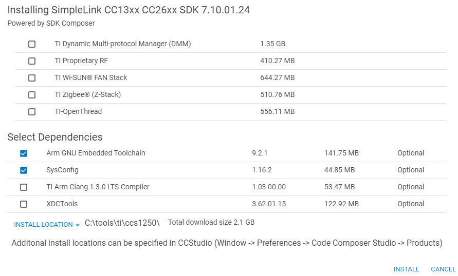
Next select the ARM GNU Embedded Toolchain and SysConfig. then press "INSTALL" button.
Once you have it installed, import the project located in embenet_demo_src folder.
You should see and navigate a project called "embenet_node_demo".
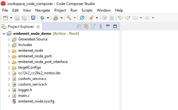
Within the project there will be following folders:
- embenet_node contains the portable embeNET Node library with headers
- embenet_node_port contains the embeNET port for the CC1312 chip
- embenet_node_port_interface contains the header files for the embeNET port (port interface)
In the main folder you'll find the application files, including main.c
Programming and debugging the LAUNCHXL-CC1312R1 boards
The boards have a built in XDS110 USB Debug Probe that can be used to program and debug the code on the microcontroller. The demo project is already configured to use this device.
Preparing the demo
There are basically two steps to prepare the demo. You need to build and deploy the code for root and for nodes.
Choosing the build target: root or node
The project has two build configurations: Root and Node. You can switch between them using the "Build Configurations" project option.
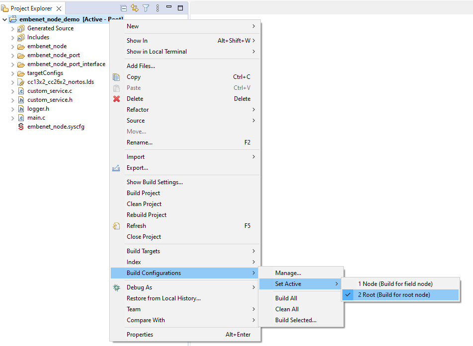
These configurations differ only in the compile-time definition IS_ROOT being set to "1" for Root and to "0" for Node.
Deploying embeNET demo application on root
Once you set Build Configuration to "Root" rebuild the project using the Rebuild project option. The application should build without errors. Connect the board you plan to use as root and hit the "Flash" button.
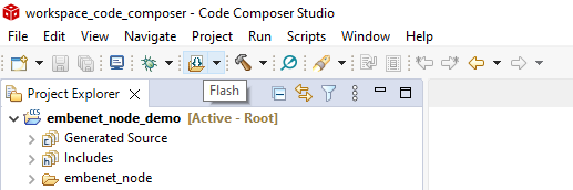
This should load the code into FLASH and begin execution.
Deploying embeNET demo application on node
Once you set Build Configuration to "Node" rebuild the project using the Rebuild project option. The application should build without errors. Connect the board you plan to use as root and hit the "Flash" button.
This should load the code into FLASH and begin execution.
Starting the Network
To start the network you need to connect the root board to the PC. It should register as two COM ports. Next go to the embenet_br folder and edit the config.json file that holds the border router configuration. The file will look similar to this:
The file has the following entries:
- serial_port - defines COM interface for the root node, in COMxx format.
- interface_name - defines the name of the network interface that will be created within the OS to communicate with the networked nodes
- panid - it is the 16-bit network identifier - it should be unique for each root
- k1 is a 128-bit, network-wide key used to authenticate information exchange in the network. This key can be specific to the network or even whole organization.
- prefix - 64-bit IPv6 prefix of the wireless network
- join_rules - set of join rules that define which nodes can join the network (see below)
Please edit the file to make sure that the serial_port entry matches the COM port registered for the root board as "XDS110 Class Application/User UART".
IPv6 address of the nodes
Each node in the network, including root has an IPv6 address consisting of two parts:
prefix:uid
where the prefix is set for the network in the config.json file and the uid is the 64-bit IEEE EUI-64 identifier, also know as the MAC address. In case of CC1312 chips this number can be read from internal registers.
Join rules
Each node that wishes to join the embeNET network needs to be authorized by the built-in Authentication Authority. The authentication process uses a pre-shared key (psk), that needs to be configured in the nodes during commissioning. In the provided demo application firmware the key is hardcoded in main.c file. During the authentication process both the uid and psk have to match what is defined in the join_rules in order to let the node join the network. However, when uid is set to 0, EVERY node with matching psk (pre-shared key) will be able to join the network. We call it the "zero rule". It is useful for testing and experimenting, however it should probably be disabled in the real deployment.
Running the border router application
The network is started once you run the border router application embenet_br.exe. The application will try to connect to the root node and then manage the network.
This is a console application that will also log a lot of information about what is going on in the network and what packets are received from the nodes. Analyzing this log may help dealing with problems, if they arise during the further development process.
Connecting the nodes
Once the border router application is running, all nodes within the communication range, should start to join the network. Be aware that this process may take couple of minutes depending on the network topology and the state of the nodes. For example: nodes that previously joined the network may require some time to notice that the border router was restarted before they attempt to join again.
Virtual network interface
While running, the border router application registers a virtual network interface within Windows. The interface name will be set according to the config.json file. You can check the presence of this interface by running the standard Windows command:
ipconfig
Also, each connected node is reachable by ICMPv6 'ping'.
Visualizing the network
The demo package includes an application that visualizes the network. It is called enms_visualizer and it is based on the ENMS service running in the background of the network. To use it simply run the application while the network is running. After a minute or so the ENMS messages will feed the application with the current state of the network, that will be visualized as a graph, spanning from the root node.
Exemplary topology with two nodes may look like this: 
Network services
A network service in embeNET, is a separated piece of functionality built around the communication over a single UDP port (rarely - multiple UDP ports). Three examples of services distributed with the embeNET stack are:
- ENMS: embeNET Network Management service that allows to gather information about the network operation from the nodes
- MQTT-SN client service that allows to use the popular MQTT publish/subscribe architecture in UDP networks and connect to standard MQTT brokers
- BOTA: Bulk-Over-The-Air service that allows to send large portions of data (for example - new firmware) between the nodes. Note that BOTA service is not available in this demo
The users however can easily develop their own services using UDP. An example of such a custom UDP service is implemented in the demo nodes.
MQTT-SN demo service
The MQTT-SN demo service uses MQTT-SN client and does three things:
- periodically publishes uptime information
- on button press publishes button click counter
- reacts to some simple text commands that control the on-boards LEDs - these commands are: led1on, led1off, led2on, led2off, etc.
Refer to Using MQTT-SN demo service for more information on how this service works and how to use it.
Custom UDP service in the demo application
The custom service implemented in the demo works on UDP port number 1234. Please note that this service works on remote nodes only - it is not available in root node. The service does two things:
- periodically sends a simple text message with counter to the border router node
- reacts to some simple text commands that control the on-boards LEDs - these commands are: led1on, led1off, led2on and led2off
There are many ways you can interact with UDP ports to test this service. One of the easiest is to use an application called UDP - Sender/Reciever app from Microsoft Store. Once you run set the mode to Sender/Receiver. Next, in the Remote IP box input the IPv6 address of the remote node that you wish to communicate with. When using the default network prefix, this IP address will have the following form:
where the UID will be the MAC address of the node.
In the Remote Port and Local Port boxes put port number: 1234
Once you hit Connect you should see incoming text messages. You can also send some commands to light the LEDs on and off.
Next steps
In order to get to know the internals of the demo and to modify or extend it refer to Internals of the embeNET demo for LAUNCHXL-CC1312R1 board
In order to test MQTT-SN part of the demo go to Using MQTT-SN demo service.
Generated on Mon Dec 4 2023 13:59:14 for Getting started with embeNET demo for LAUNCHXL-CC1312R1 board by